A heat sink is used in electronic devices to dissipate heat and prevent overheating. It is typically made of a metal such as aluminum or copper. It absorbs and transfers heat from the device’s central processing unit (CPU) or other heat-generating components. Heat sinks work by increasing the surface area available for heat transfer and using fins or other structures to increase the flow of air or other cooling medium over the surface of the heat sink. This helps to keep the device operating at a safe temperature and prevent damage from overheating.
In many applications, the device is an electronic component (e.g. CPU, GPU, ASIC, FET ,IGBT etc.) and the surrounding fluid is air. The device transfers heat to the heatsink by conduction. The primary mechanism of heat transfer from the heatsink is convection, although radiation also has a minor influence.
There are two distinct types of convection:
Natural convection – where the movement of the fluid particles is caused by the local changes in density due to transfer of heat from the surface of a solid to the fluid particles in close proximity.
Forced convection – where the movement of the fluid particles is caused by an additional device such as a fan or blower.
Heatsinks are designed to significantly increase the contact surface area between solid and fluid, thereby increasing the opportunity for heat transfer. A typical ASIC may have a surface area in contact with air of only 1600mm2. The surface area of a typical heatsink used to cool that device may be 10 or 20 times that value.
HOW DOES A HEATSINK WORK?
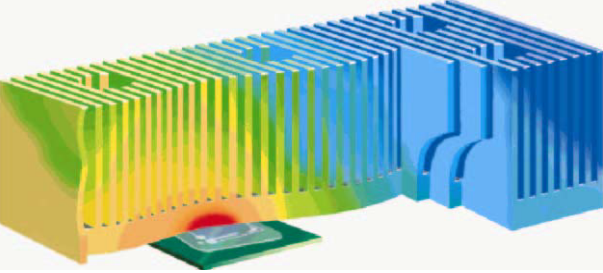
When electronic components operate, they generate heat due to the flow of electricity through them. This heat must be dissipated to prevent the parts from overheating and failing. A heat sink works by absorbing this heat and spreading it out over a larger surface area, allowing it to dissipate more efficiently.
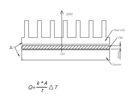
The heat sink is typically attached to the electronic component using a thermal interface material, such as a thermal paste or pad. This material helps to transfer the heat from the component to the heat sink.
Once the heat is transferred to the heatsink, it dissipates into the surrounding air through convection. The larger the surface area of the heat sink, the more efficient it is at dissipating heat.
Adequate cooling is essential for electronic devices, and heatsinks are an important component of any cooling solution. At Radian Thermal Products, inc., we are proud to be one of the leading heatsink suppliers in the industry, offering a wide range of high-quality products and exceptional customer service. Contact us today to learn how we can help meet your cooling needs.
HEATSINK CONSTRUCTION
There are many designs for heatsinks, but they typically comprise a base and a number of protrusions attached to this base. The base is the feature that interfaces with the device to be cooled. Heat is conducted through the base into the protrusions. The protrusions can take several forms, including:
Heatsinks are usually constructed from copper or aluminum. Copper has a very high thermal conductivity, which means the rate of heat transfer through copper heatsinks is also very high. Whilst lower than that of copper, aluminum’s thermal conductivity is still high and it has the added benefits of lower cost and lower density, making it useful for applications where weight is a major concern.
HEATSINK PERFORMANCEThe performance of heatsinks are a consequence of many parameters, including:
> Geometry
> Material
> Surface treatment
> Air velocity
Thermal Contact Resistance
1. Interface Characteristics
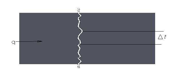
When a heat source is brought into contact with a heatsink, the solid surfaces do not achieve perfect contact in practice.
Although both electronic components and heatsink bases are manufactured to be flat and smooth, their surfaces are inherently rough at the microscopic level. As a result, actual contact occurs only at a limited number of discrete points, leaving numerous microscopic air gaps between the device and the heatsink.
2. Heat Transfer Across the Interface
The gaps between the contact points are typically filled with air. Heat is transferred across these gaps through:
However, since air has a very low thermal conductivity, these gaps significantly reduce the efficiency of heat transfer from the device to the heatsink.
Compared to an ideal condition of perfect contact, this additional resistance to heat flow is defined as thermal contact resistance.
3. Impact on Thermal Performance
Thermal contact resistance plays a critical role in overall thermal performance.
If not properly managed, it can:
- Increase junction temperature
- Reduce cooling efficiency
- Affect system reliability
Therefore, it must always be considered in thermal design and analysis.
4. Methods to Reduce Thermal Contact Resistance
To minimize thermal contact resistance, the following approaches are commonly applied:
- Increasing the contact pressure between mating surfaces
- Improving surface flatness and finish
- Applying thermal interface materials (TIM)
5. Role of Thermal Interface Materials (TIM)
Thermal interface materials are used to fill the microscopic air gaps and improve heat conduction.
By filling these voids, TIMs:
- Increase the effective contact area
- Provide additional thermal conduction paths
- Significantly improve heat transfer efficiency
6. Material Selection Considerations
In practical applications, selecting the appropriate TIM is essential. Common options include:
- Thermal grease
- Thermal films
- Thermal pads
The selection should be based on:
- Thermal performance requirements
- Mechanical constraints
- Assembly conditions
Heatsink performance is characterized by its thermal resistance. This parameter can be thought of as the difference in temperature between the air around the heatsink and the device surface in contact with the heat sink per unit of input power. Thermal resistance is denoted by the symbol θ and has the unit °C/W.
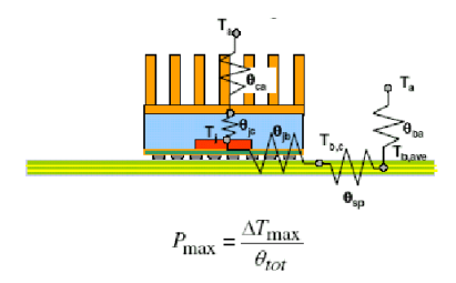
The junction temperature (TJ) is the temperature of the hottest part of the device. This is the critical temperature for its correct operation. The case temperature (TC) is the temperature of the surface of the device which is in contact with the heatsink assembly. TC is lower than TJ due to the junction-to-case thermal resistance (θJC). The performance of the heatsink assembly is defined by the case-to-ambient thermal resistance (θCA). This is the difference in temperature between the device surface (TC) and the surrounding air (TA) for a unit of input power.
The increase in TJ over TA for each Watt of thermal power the device generates is the sum of θJC and θCA.
HEATSINK MANUFACTURING METHODS
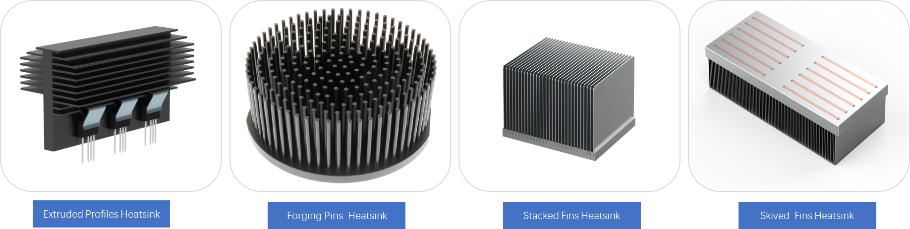
Heatsinks can be manufactured in a variety of ways depending on the required performance, cost and volume. These include:
Machining – where a CNC machine is used to cut the metal
Extrusion – where metal is heated and pushed through a mold
Forging – where metal is heated and shaped by pressurization
Stamping – where the metal fin is cut, and then soldered onto the base
Skiving – where a blade is used to slice, and push up the single block of metal
For more complex thermal issues, heatpipes and vapor chambers may be employed within the heatsink assembly. These devices are sealed objects containing a fluid (typically water) and utilize the release of heat during fluid phase changes to vastly increase their conductivity when compared to a solid metallic object of the same geometry.
Radian Thermal Products offers all these manufacturing techniques and we can therefore provide an unbiased approach to each thermal requirement.


